|
||||||||||||||||||
| This page last modified: 2009/04/23 The 3D work finished: 2008/09/25 |
||||||||||||||||||
|
Faking Anisotropic Effect
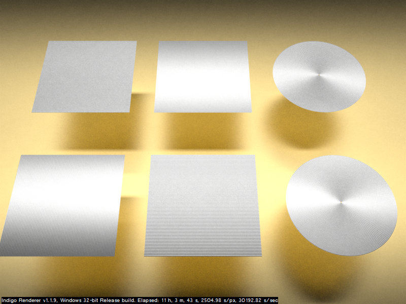
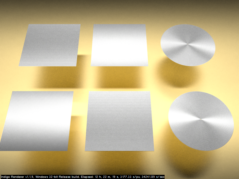
I modelled something that has a switch button in Blender 2.47 and I used Indigo 1.1.9 exporting with Blendigo 1.1.7 to get a photorealistic render of the model. I tried to setup the material of the button for metallic reflection with Blendigo, but it didn't look like the real metal button. The reason is that it should have kind of anisotropic reflection on it. Using a bump map At this time, Indigo doesn't have the settings yet that allow you to setup anisotropy in an easy way, according to some of threads in Indigo forum. Meanwhile, there are also some posts there where someone suggested a good way to fake the effect by using a bump map, and I decided to take a test of it. The following image is what I got. The effect for anisotropy can be seen, but it looks a bit less realistic because of kind of too heavy grooves.
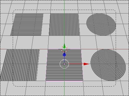
Here is the image that shows how the bump map has arranged on the planes.
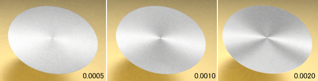
The Three Parameters that Affect Anosotropy It's all a fake and doesn't look so realistic, but even so, it has a good point, you can easily tweak the effect. The three parameters, IOR, Exponent, and B in Bump map in Blendigo 1.1.7, affect anisotropy well. Getting IOR high will make the reflection bright, getting Exponent high will make the reflection thin, and getting B high will make anisotropic effect strong. I'm going to show how the parameter Exponent affects anisotropy. The following three images were rendered with Exponent 0.0005, 0.0010, 0.0020 respectively. It can be seen that the higher Exponent makes reflection thinner.
|
||||||||||||||||||